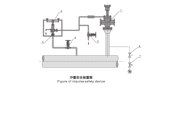
Description:
Installation instruction:
1. The main safety valve, A49Y-PW54-10V, DN125, and the impulse safety valve , A49Y-PW5410V, DN20, should be installed together. The distance between the outlet pipe of the impulse safety valve and the inlet pipe of the main safety valve should be maintained as relatively long and the distance between the electric contact pressure meter and the inlet pipe of the. main safety valve should be no less than 5 times of the diameter of the inlet pipe, for fear that the precision of the meter and the impulse safety valve may be affected by the steam discharging process of the main safety valve.
2. Before the installation of the impulse safety valve, the pipelineshall be cleaned first.
3. The main safety valve and the impulse safety valve must be positioned vertically, After the installation and the welding the mainsafety valve, it shall be under partial hear treatment.
4. The main safety valve shall be fastened upon the framework.which sustains the counter-reaction force produced in the steamdischarging process of the main safety valve. The exhaust pipe of the main safety valve shall be supported with a special gallow lest the force of its weight and action would be directly apply to both the main safety valve and the flange that is connecting them. At the lowext point of the exhaust pipe water drainage shall be taken into consideration to avoid producing water hammer when the main safety valve is discharging steam.
5. The impulse safety valve and the electromagnets shall be placed together on a special gallow. The juncture of the upper lever of the valve and the electromagnets shall be flexible, with no phe-nomenon of seizure. The impulse safety valve shall be installed in a place with little dust, dry air and convenient maintenance and de-bugging, and where no vibration occurs, Its ambient temperatur e shall not higher than 70 , and its relative humidity not more than 80%.
6. To ensure the ajile working of the impulse safety valve, the distance between the circular arc part of the head of the seat re-turning lever and the end of the pressure bar of the valve shall be adjusted to the length of the actual traved of the valve adding 1 mm (adjusted by the M10X40 fastening screw at the top of the cap).
 产品名称:冲量安全


